Deep excavation design in Philadelphia’s dense urban core demands more than just a standard shoring calculation. The city’s subsurface profile, shaped by the Atlantic Coastal Plain and punctuated by buried paleochannels of the Delaware and Schuylkill rivers, introduces abrupt transitions between dense gravels and soft organic silts within the same block. IBC Chapter 18 and ASCE 7-22 require that lateral earth pressures, groundwater control, and adjacent structure protection be evaluated as an integrated system, not as separate checks. In practice, this means every excavation over 15 feet in Philadelphia’s Center City or University City districts triggers a mandatory support-of-excavation submittal reviewed against both the building code and the Philadelphia Administrative Code. The engineering team correlates historical boring logs from PGW or PWD archives with modern in-situ testing to map the pressure boundary before the first bucket hits the ground. When we encounter the characteristic micaceous sand of the Pensauken Formation, we often combine the CPT test for continuous stratigraphic profiling with instrumented tieback load cells to confirm design assumptions during construction.
Philadelphia’s interbedded Coastal Plain deposits demand an excavation design that treats groundwater and lateral support as a single coupled problem, not two separate scopes.
Scope of work in Philadelphia
- Lateral earth pressure coefficients calibrated to the drained friction angle of the Pensauken sand (φ’ typically 30°–34° at medium density).
- Groundwater cutoff evaluation comparing sheet pile toe embedment into the clay of the Merchantville Formation versus the cost of a jet-grouted bottom plug.
- Adjacent structure settlement analysis using the Clough and O’Rourke envelope, correlated with building condition surveys per Philadelphia L&I requirements.
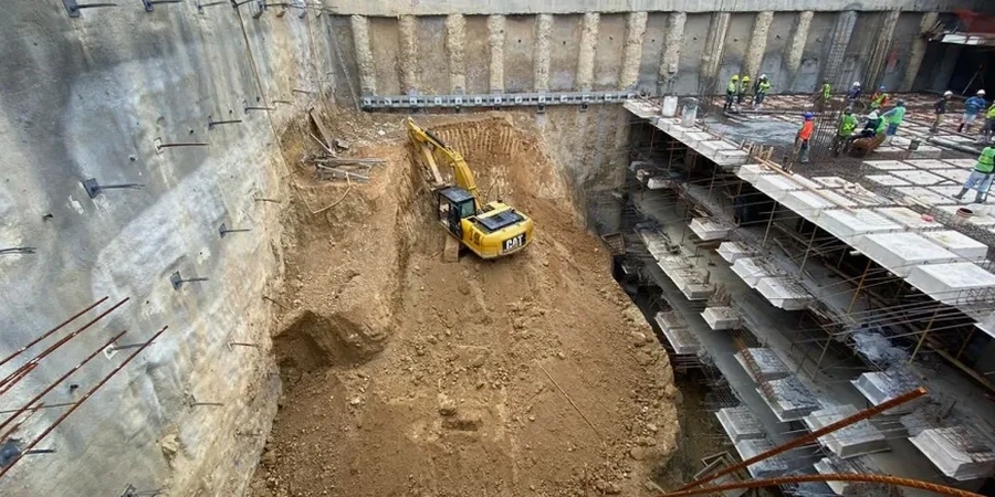
Local geotechnical conditions in Philadelphia
Philadelphia’s freeze-thaw cycles and summer thunderstorms introduce a seasonal risk that many excavation designs underestimate. The urban fill layer, already loose and heterogeneous, becomes unstable when saturated snowmelt percolates through it in February and March, increasing lateral pressures on soldier pile lagging by 15 to 20 percent above the drained design value. Meanwhile, the dense clay layers that serve as a groundwater cutoff in dry months can desiccate and crack near the excavation face during the humid summer, creating preferential seepage paths that bypass the dewatering system. A design that works in October might struggle in April if the seasonal groundwater fluctuation—often 4 to 6 feet in Philadelphia—was not modeled in the seepage analysis. We address this by running transient flow models in SEEP/W with seasonal boundary conditions, rather than relying on a single steady-state water table. For excavations deeper than 30 feet near SEPTA tunnels or the Market-Frankford Line, the vibration monitoring trigger levels are set per the transit authority’s guidelines, typically 0.5 in/sec peak particle velocity at the tunnel lining, which governs blasting and compaction sequences.
Our services
Deep excavation projects in Philadelphia’s constrained urban sites require a focused set of engineering services that go beyond generalized geotechnical reporting. The work we coordinate centers on two interdependent specialties.
Support of excavation design and shoring engineering
We develop sealed shoring plans for soldier pile and lagging, secant pile, or diaphragm wall systems, with tieback and internal bracing designs verified against the lateral earth pressure profiles of the Coastal Plain formations. Each submittal includes a global stability analysis, basal heave check in soft clays, and a construction sequencing plan coordinated with the contractor’s means and methods.
Dewatering and groundwater control engineering
We design staged dewatering systems for Philadelphia’s layered aquifer conditions, specifying wellpoint spacing, deep well pump capacities, and cutoff criteria for sheet pile or slurry wall toe embedment. The analysis includes a settlement influence zone assessment for adjacent row homes and historic masonry structures within the zone of influence.
Q&A
What triggers a support of excavation (SOE) submittal in Philadelphia?
Under IBC 2021 Chapter 18 and the Philadelphia Administrative Code, any excavation deeper than 5 feet that is adjacent to a public right-of-way or an existing structure requires a sealed SOE design. For excavations deeper than 15 feet, a full engineering analysis including lateral earth pressures, groundwater control, and adjacent structure protection is mandatory, reviewed by the Department of Licenses and Inspections.
How do you handle the urban fill layer in the excavation design?
Philadelphia’s urban fill is highly variable, containing brick, timber, and coal ash. We treat it as a separate design stratum with conservative strength parameters (c’ = 0, φ’ = 24°–28°) and check for perched water. Lagging design incorporates the potential for voids behind the flange due to fill collapse, and we specify controlled low-strength material (CLSM) backfill behind the upper lagging boards where fill is loose.
What is the typical cost range for a deep excavation design in Philadelphia?
The engineering design fee for a deep excavation project in Philadelphia, including shoring plans, dewatering analysis, and sealed submittal drawings, typically ranges from US$2,150 for a straightforward single-family lot excavation to US$8,690 for a complex multi-level commercial cut with tiebacks and adjacent SEPTA infrastructure coordination. The final scope depends on the depth, adjacent structures, and groundwater conditions.
How is the Wissahickon Schist bedrock handled in the bracing design?
When the Wissahickon Schist is encountered within the excavation depth, the bracing strategy shifts from a soil pressure envelope to a rock mechanics approach. We evaluate the rock quality designation (RQD) from core logs and design rock anchors where the schist is competent, or specify a soldier pile socket into the weathered rock zone if the RQD is below 50 percent. The transition zone between soil and rock is the most critical detail for wall alignment.